What's Inside a Baofeng Rubber Ducky Antenna? |
Have you wondered what's on the inside of a Baofeng UV-5R rubber ducky antenna? I did, so I took a few of them apart. Below are the photos of what I found.
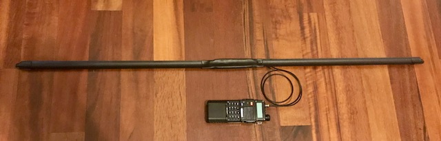
This is a VHF/UHF antenna from a UV-5R. There are several Baofeng models based on the UV-5R (like the 8W BF-F8) and the antennas appear to be the same from the outside. But there are some pics on the internet of some Baofeng rubber duckies that don't look like this one, so the design changed at some point. Bob K0NR has a good picture of an older Baofeng antenna...and a couple other antennas, too.
Also, the Baofeng UV-5RX3 is a tri-band radio covering 2m, 1.25m, and 70cm. I have two of these, and they both shipped with two antennas--one optimized for 2m/70cm, and a slightly shorter one optimized for 1.25m. I did not cut apart a 1.25m antenna.
I didn't take apart any more advanced ones like the Nagoya NA-771. If you'd like to donate one for science....haha!
So without further ado....
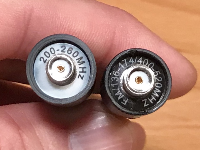
Pic 1: 1.25m rubby ducky on left, 2m/70cm on right.

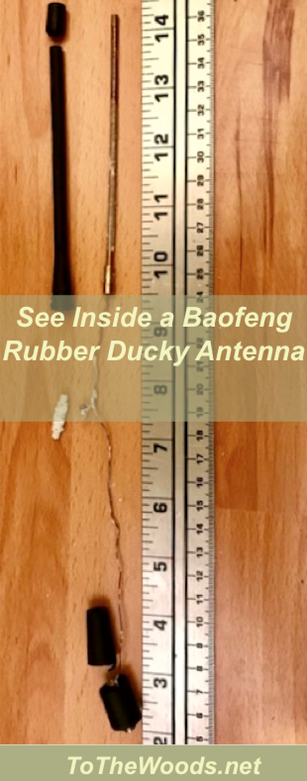
Pic 2: I started by cutting around the bottom of the sheath and sliding it off the twisted wire antenna. A rubbery white adhesive secured the antenna inside the sheath.
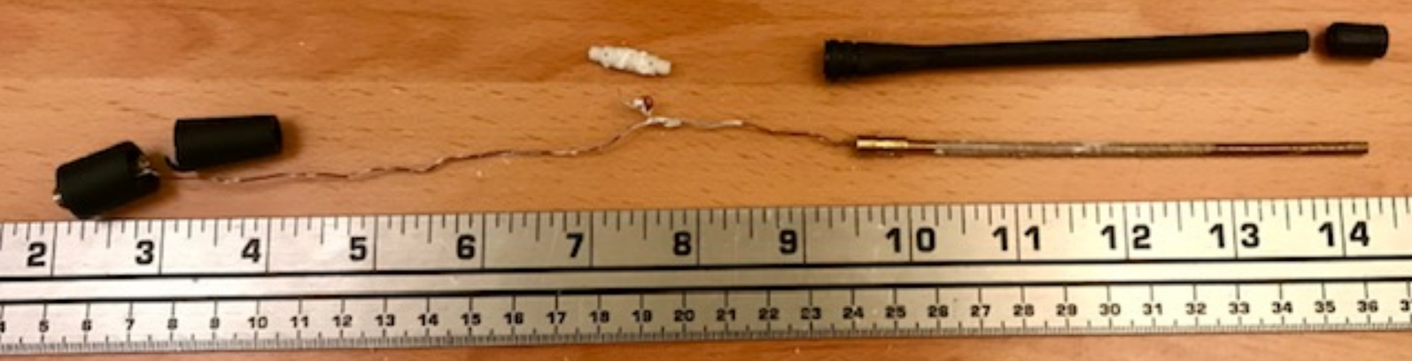
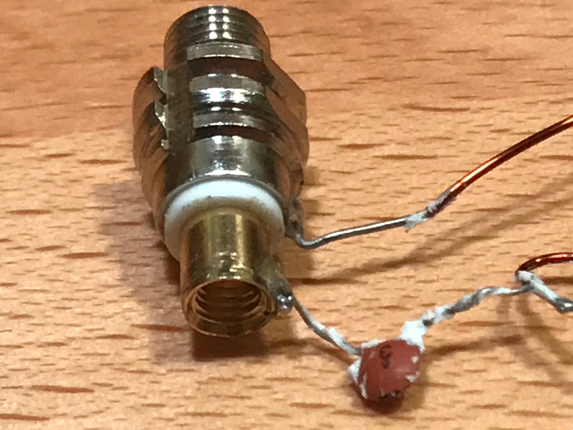
Pic 3: When I unscrewed the antenna, I found a copper wire coiled around a plastic adapter. The plastic adapter connects the coiled wire antenna to a metal adapter inside the base of the sheath. The metal adapter has a female SMA on one end.
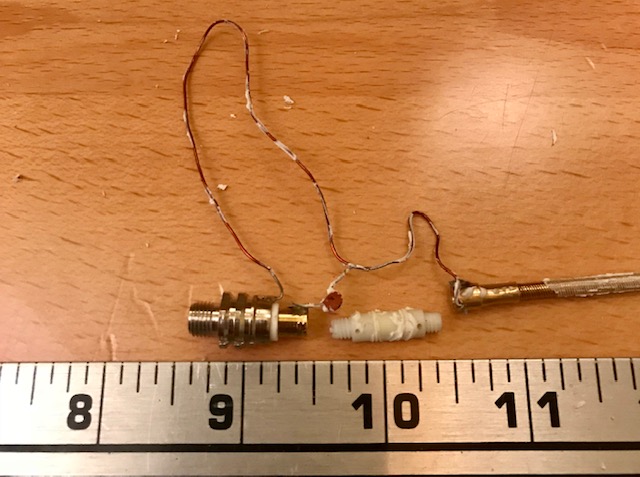
Pic 4: Here's a close-up of the parts inside the plastic sheath. You can see the metal adapter with the SMA Female jack on the far left. The ridges in the metal adapter match up to ridges formed in the plastic sheath so it can't be pulled out of the sheath; it must be cut out. There's a white sheath inside the metal adapter insulating the ground from the driven element.
The copper wire is soldered to the ouside (ground) of the metal adapter on left end in the picture, and to the antenna on the right end. A small capacitor is soldered in the middle of the wire, between the antenna and the driven element. This is critical information if you're trying to reuse the rubber ducky's base to build your own antenna. I tried this before I knew there was a capacitor inside and the SWR made the antenna unusable.
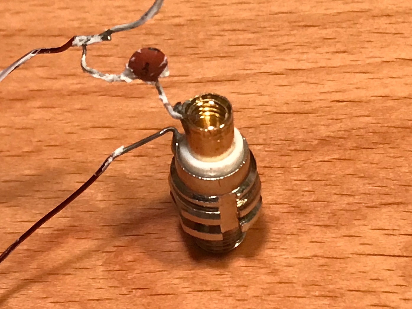
Pic 5: Close-up of where the coiled wire screws into the metal adapter.
When I made the DIY antennas, I had a hard time soldering anything onto the copper-colored sleeve where the antenna screws in. If I heated up the sleeve enough to get the solder to melt, the white insulation melted. And if I tried to heat the solder instead of the copper sleeve, it wouldn't stick. I need to solve this problem if I'm going to use these as a base...but I'll probably just get the parts to build from scratch. If you have a solution (or can help me learn how to solder better), please shoot me an email.
Pic 5: Alternate view of where the coiled wire screws in.
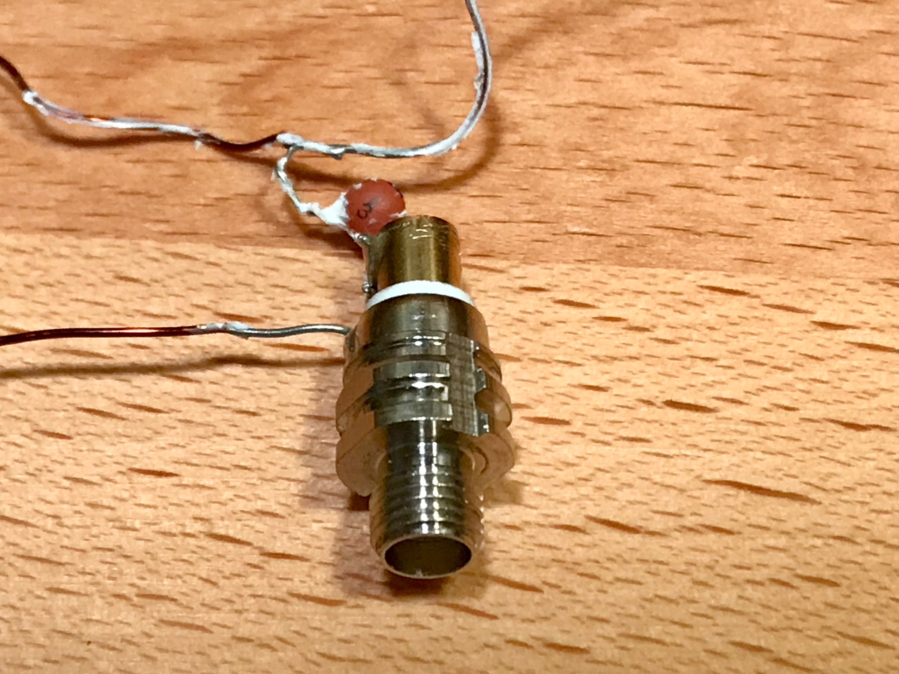
Pic 6: Female SMA end of the metal adapter.
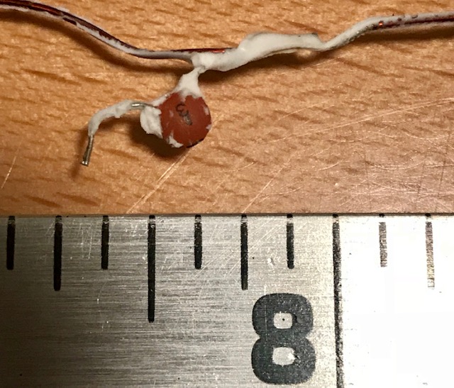
Pic 7: Close-up of the capacitor.
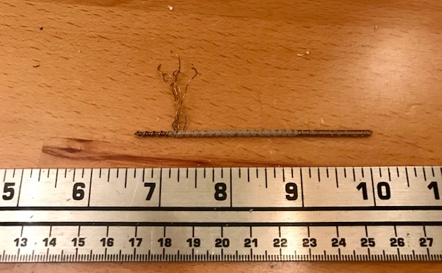
Pic 8: Close-up of the coiled wires. Electrons travel on the surface of the copper, and a bunch of small coiled wires has more surface area than a single large wire. This makes the antenna much more effective for a given size.
I uncoiled the wires enough to see that there are at least three layers of coils, with each one twisting opposite the ones around it. I.e., the outer wires coil clockwise and the ones underneath coil counter-clockwise (or vice versa if you look at it from the other end).