How to Make a Half-Wave Dipole Antenna from a Tape Measure
I wanted an antenna better than what came on the Baofeng, and even better performance than the Nagoya NA-771. (I also just wanted to build something so I could learn how this stuff works.) I knew a half-wave dipole would get better reception, and I knew about the rat tail ground plane to approximate a dipole...but I wanted something a little different.
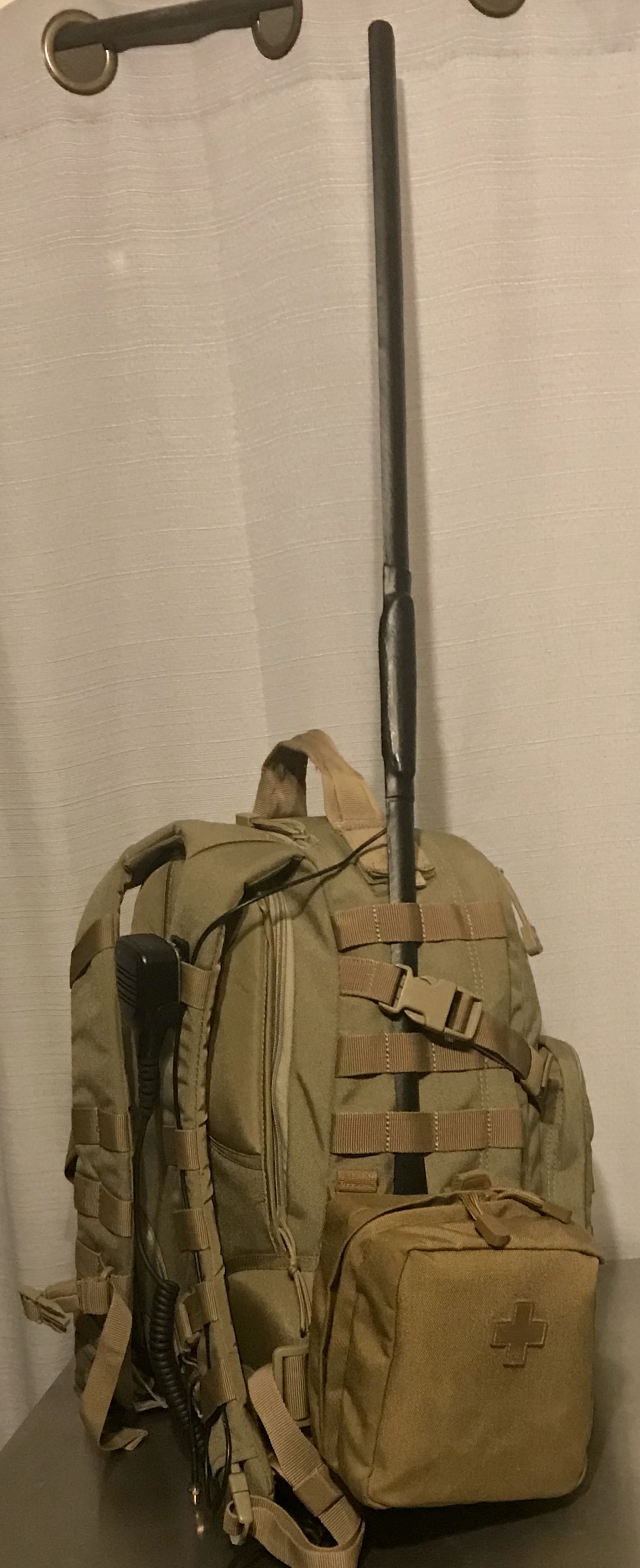
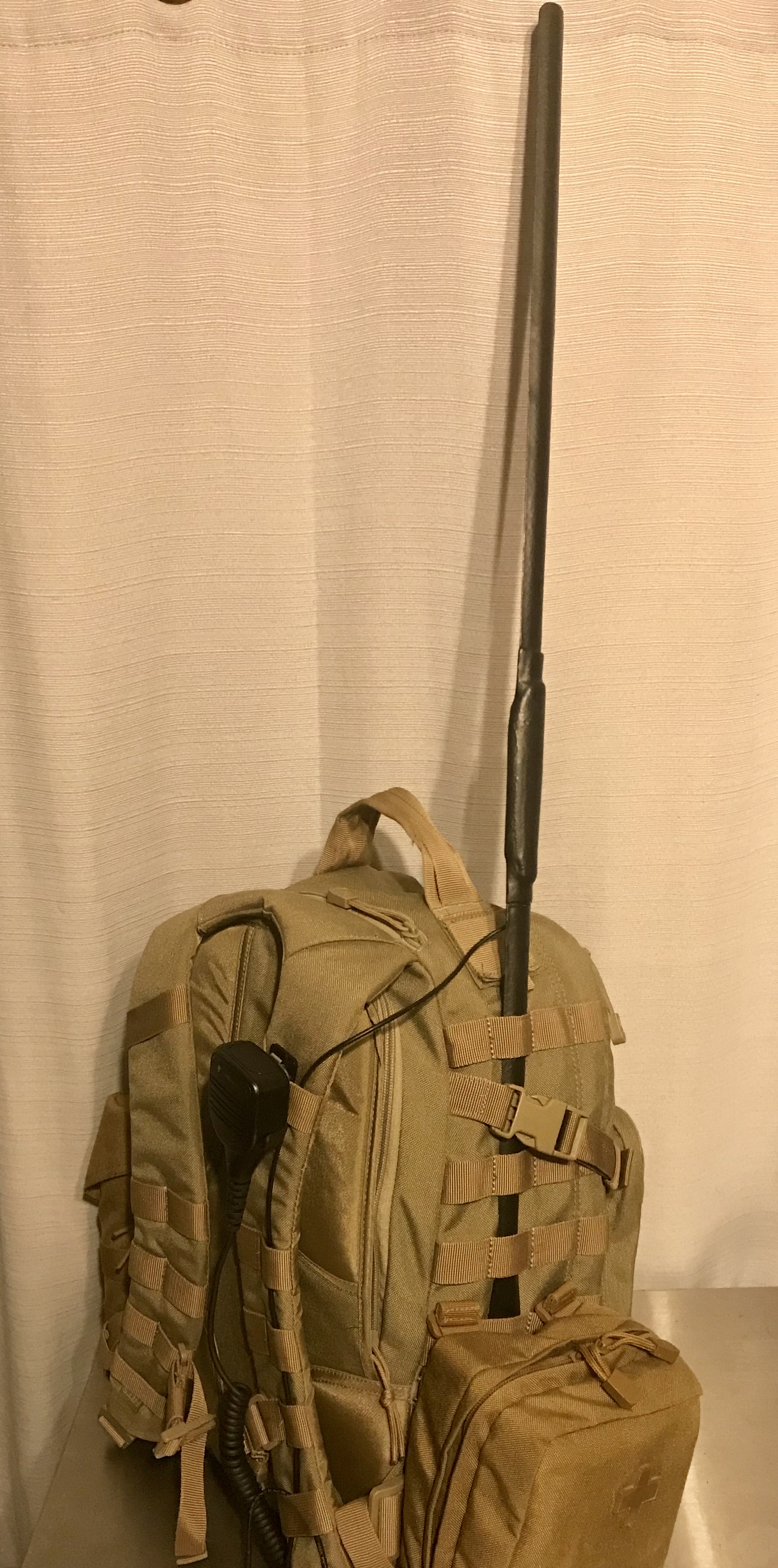
Since tape measures are flexible, I can mount this to a backpack and keep it folded down when I don't need it, then pop it up with very little effort while I keep walking. With handheld mic on the shoulder strap, I can leave the radio attached to my belt so it's even more convenient...and still get better reception than an antenna attached to the radio.
But also, since it's more sturdy than a wire, I can use the ground element to extend the driven element higher. I don't want anything to touch the driven element when I transmit because when I tested it on an antenna analyzer, I saw dramatic changes in standing wave ratio (SWR) based on where I touched the antenna during transmission. If I extend the antenna without anything touching the driven element, I avoid this problem.
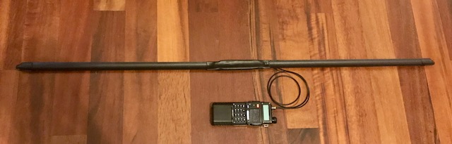
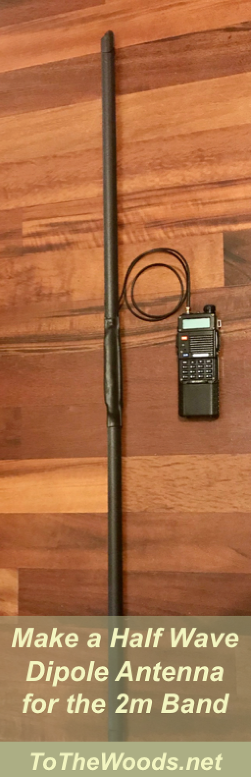
The End Result
Materials required:
- (2) 19" pieces of tape measure. I used the Stanley Fat Max because it was the cheapest heavy duty one I found at Home Depot.
- (2) 4" pieces of tape measure.
- Heavy duty 5/8" shrink wrap.
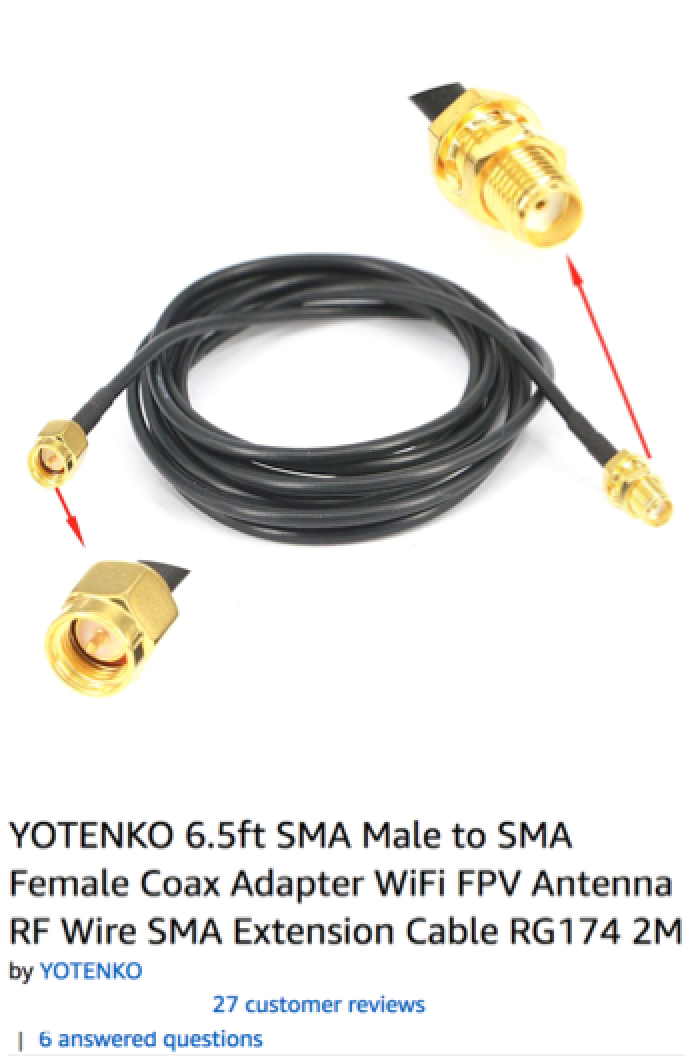
- Antenna relocation cable (or the means to build your own). Mine is similar to this one.
- Sandpaper.
- Electrical solder and soldering iron. I use rosin core, but some people say lead core solder is easier to work with and makes better connections. Up to you...just be extra careful about breathing the fumes if you use lead core.
- Heat gun (or other way to activate the heat shrink).
- Flex-Seal, as seen on TV!
.
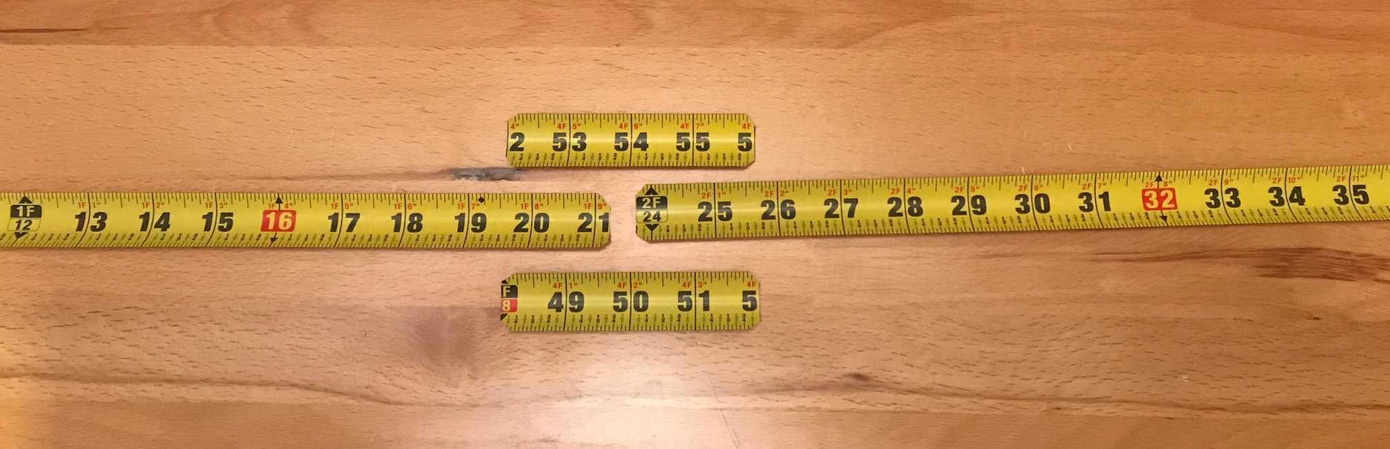
Pic 1: I started with two 19" pieces of tape measure for the dipole arms, and two 4" pieces to brace the arms together when connected. The arms must be separated, so the braces will give structure to the antenna.
I cut the tape measure with heavy duty scissors, and then trimmed the sharp corners so they wouldn't damage anything. Be careful doing this because the sharp corners pop off and fly across the room when they're cut. I did it inside a trash can to try to trap the little shards of metal...that helped a little but some of the shards still bounced out onto the carpet.
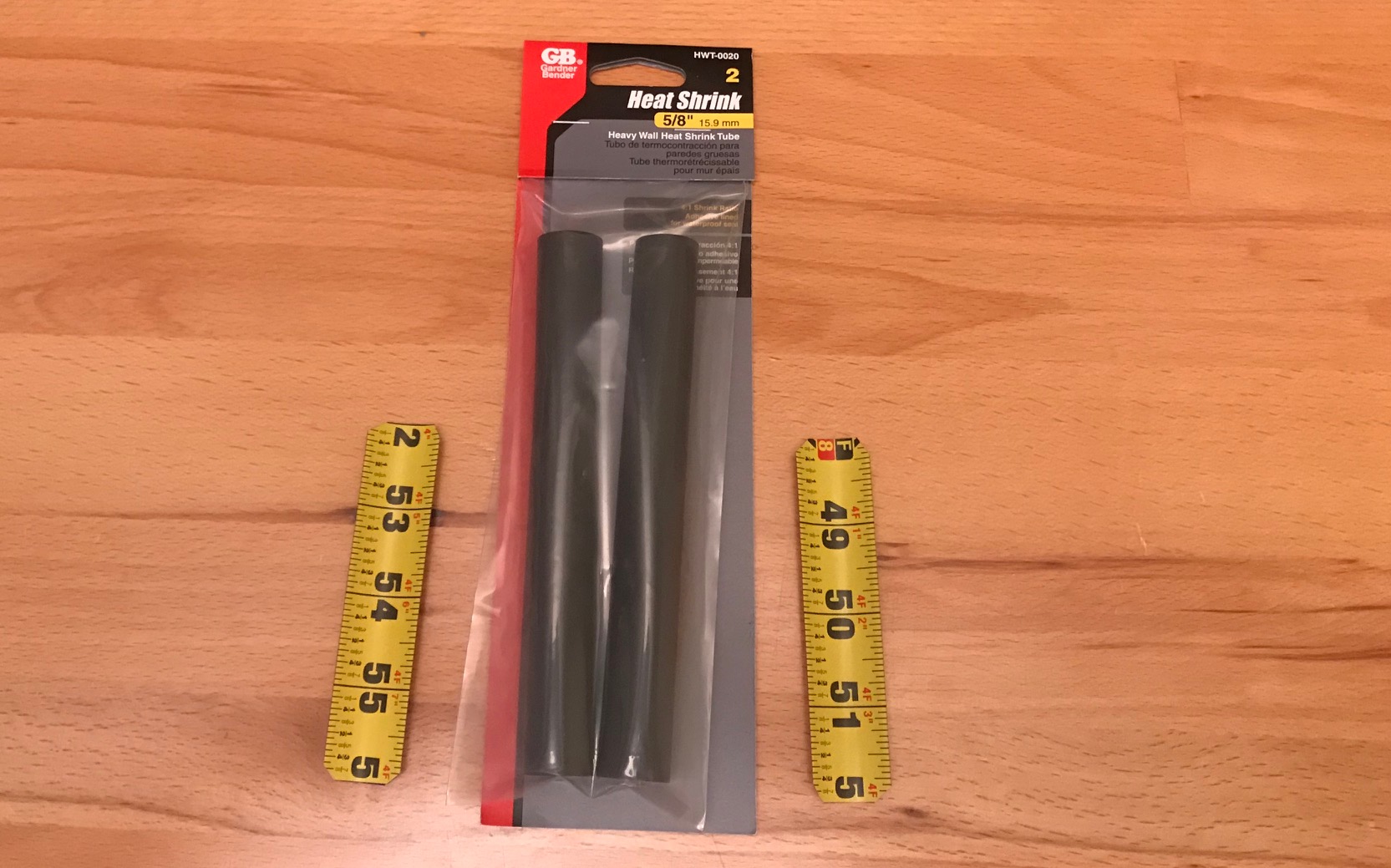
Pic 2: I insulated the braces with this heat shrink so they wouldn't conduct energy between the driven and ground elements.
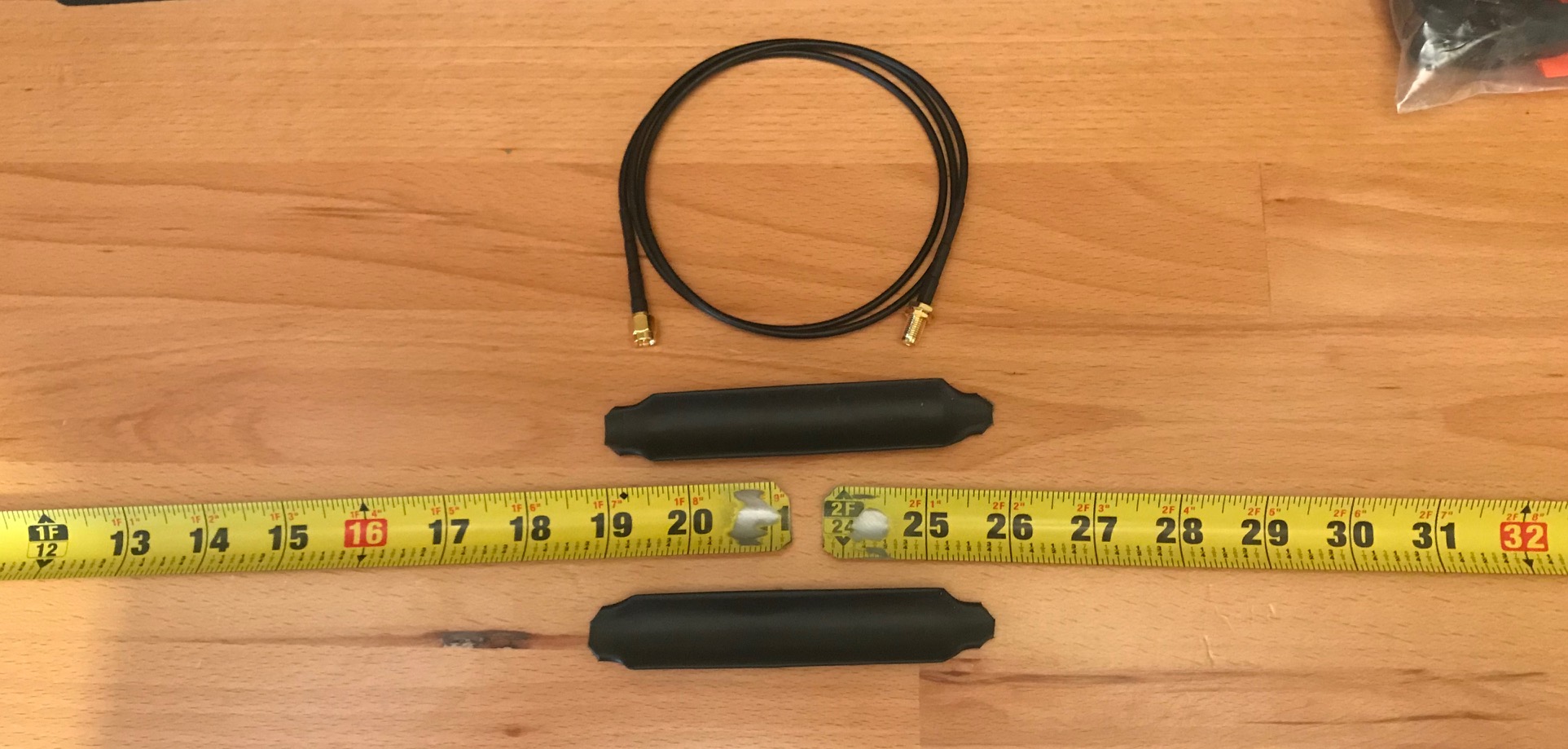
Pic 3: This pic shows the antenna relocation cable I used to connect the dipole arms, the braces after I covered them with the heat shrink (I also trimmed the heavy duty heat shrink), and the dipole arms.
It's important to sand the paint off the tape measure to get a good electrical connection when you solder the wires onto the arms.
Heat shrinking a tape measure is tricky because the shrink wrap doesn't want to conform to the tape's concave shape. I ended up cutting two more pieces of tape measure to act as a press and smash the heat shrink down onto the inside of the tape measure, and it helped that the heat shrink had adhesive on the inside. It wouldn't have formed well without that.
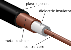
Pic 4: Since the female SMA connector attaches to the Baofeng, I cut the male SMA connector off the antenna relocation cable and stripped the ends. See the pic below for a cross section of coaxial cable. The inner conductor (labeled "center core" in the pic below) is the antenna's driven element, and the outer shield is the ground element. These need to be soldered to the dipole arms. It doesn't really matter which end is which but you'll want to keep track of the driven element for later.
Pic 5: This pic shows one brace on the back side of the dipole arms, and the feed line oriented toward the ground arm. Once both braces are installed, slide the last piece of heat shrink (top of pic) over the whole assembly...this is why the feed line needs to be pointed toward the ground element.
Pic 6: I wanted some more insulation on the solders, so I sprayed it with Flex-Seal before putting the front brace on. This also acts as an adhesive to keep the elements in place so they don't slide together and touch after assembly.
Pic 7: Final piece of heat shrink installed. Be sure the elements aren't touching when you apply the heat.
Pic 8: Not entirely necessary, but I put some heat shrink on the ends to be sure they weren't too sharp. I ended up cutting these off later anyway, when I had to shorten it to get resonance at a good frequency. I don't remember exactly but I think it's tuned to 146.00. I left this pic in the instrutions because you can see it the ends in the next photo.
Pic 9: Finished product, before trimming to tune it. I sprayed the whole thing with a couple coats of Flex-Seal so it wasn't so ugly, and to add a little more water resistance to the center feed.
At this point, it's time to test. Put it on an antenna analyzer, and trim the ends until it resonates at your desired frequency. (You can also do the math to figure out how much to trim; I recommend trimming a little less than calculated so you can fine-tune it and don't accidentally take off too much.
I have tested this antenna by listening to the same transmissions from the same location with different antennas, and this transmits and receives better than the rubber ducky that comes with the Baofeng, and better than the Nagoya NA-771 with a rat tail. I frequently get reports of "full quieting into the repeater" from an area where the NA-771 sometimes gets reports of "4 out of 5" on the same radio.
The standing wave ratio (SWR) measures a flat 1.4 across the 2m band.
Of course, it's a lot easier to just buy the Nagoya NA-771 from Amazon, and it's perfectly functional. (But this is a lot more fun and it works better!)
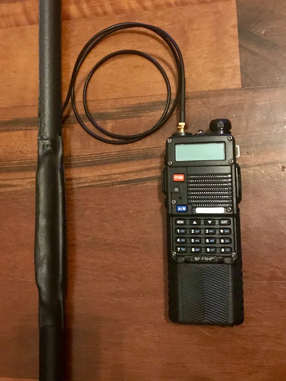
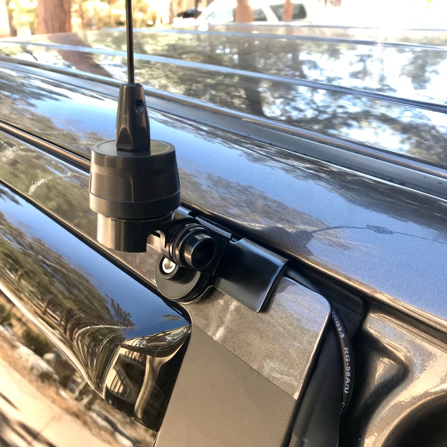
Pic 10: Detail of center feed and radio connection.
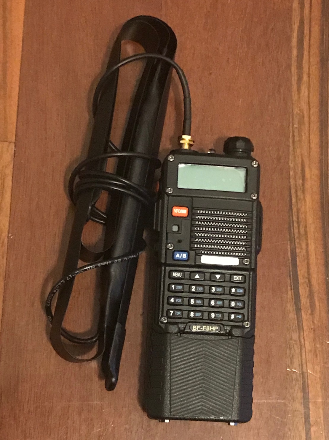
Pic 11: It folds up pretty small.
Final Note: Using so much heat shrink is probably overkill. If I make another one, I'll probably skip the heat shrink around the braces. I'd solder the arms together, then put heat shrink over that assembly, then put the bare braces in front of and behind the assembly, then heat shrink that whole assembly together. This would eliminate one whole length of heat shrink, taking about 1/3 of the thickness away from the center.
Please email me with any questions about this project and I'll try to answer them!
Back to the Amateur Radio Homepage