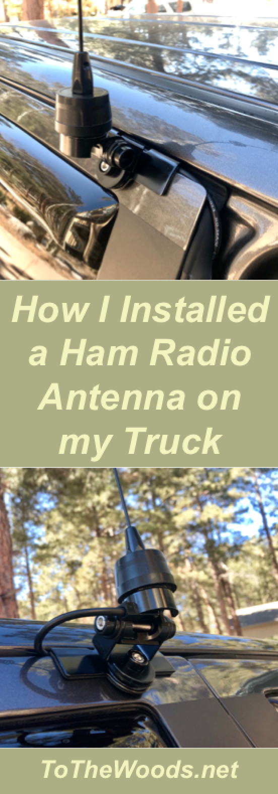
How I Installed a Ham Radio Antenna on my Truck (VHF/UHF)
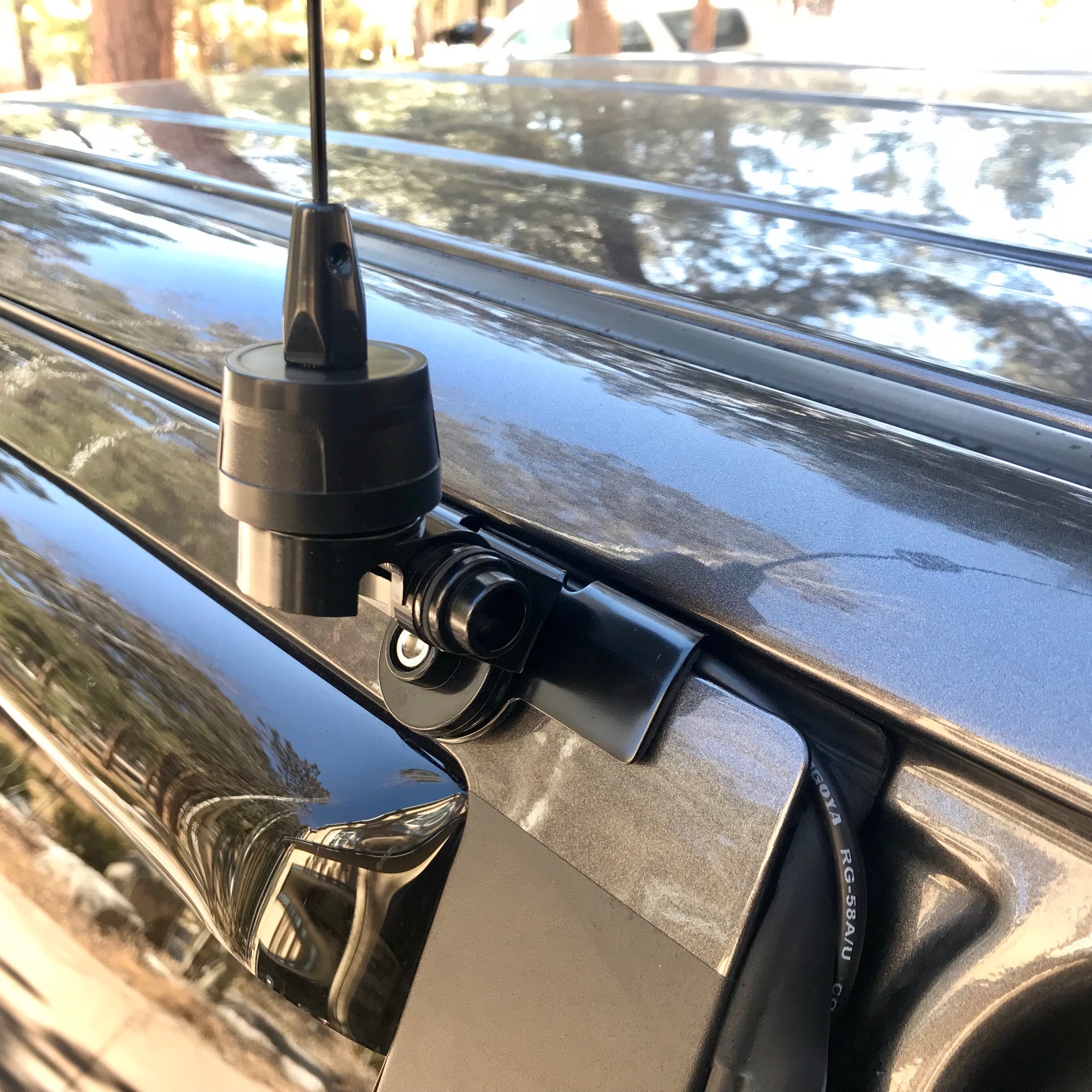
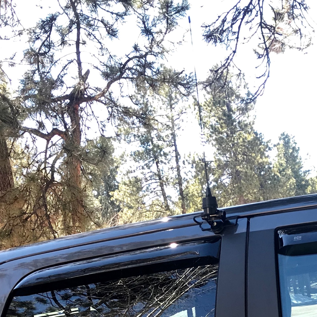
The End Result
I wanted to mount an amateur radio antenna on my truck that was more permanent than the magnetic mount on I already had, but I had a few specific design requirements for the project.
Semi-permanent install: no need to set it up when I want to use the radio
No permanent modification to the vehicle
Clean install: no cables cluttering the cab
Effective use of 2m/1.25m/70cm bands, including ground plane considerations
As the common ham radio saying goes, everything is a compromise and this is no exception, but I found a compromise that works for me in the Nagoya NMO-72 19.25" Antenna NMO Mount Dual Band VHF, UHF (145/440Mhz) mounted to the truck with a Nagoya RB-700N Heavy Duty Universal NMO Lip Mount (Multi Axis Adjustable). This combination features an NMO mount that is more weather-resistant than the magnetic mount I already had, would do less damage to the vehicle than the magnetic mount (because dirt gets trapped under the magnetic and abrades the paint), and would fit well on top of one of my doors.
I chose to put mount this on top of the rear passenger door, at the forward edge. That's a good location for me for a few reasons. First, that door gets opened less often than all the others, so there's less opportunity for damage to the install, snagging a cable, etc. Second, I put it on the leading to minimize cable routing complexity and, more importantly, so the ground plane is equalized forward and aft of the truck. I know that radio waves won't reflect as strongly on the passenger side of the vehicle so my transceiving distances will likely be shorter than on the driver's side, but at least I'll have good coverage both in front of and behind the truck. This will be good for hearing traffic reports from vehicles in front of me, and for being able to relay information to travelers behind me.
After install, I did a quick radio check while driving down the interstate and got a report of "full quieting" from a repeater off the passenger side of the vehicle, so it works even on the weak side. Although to be fair, the repeater is on top of a mountain so it was a directly shot to my antenna. But still, it works!
Update: Using the Antenna during a Blizzard
On 13 March 2019, Colorado experienced a "bomb cyclone" blizzard with record-setting winds, 600+ stranded people staying in shelters, and some homes literally destroyed. First responders rescued more than 1000 people, and hundreds of vehicles were stuck on the roads.
As it turned out, my son had to work--and then he couldn't get back home. So I had to go out during the worst part to get him back to his house! I shouldn't have been driving, but it was the least-bad option because even the rescuers were backed up at this point. And I have some experience driving in poor conditions--and the ham radio with a decent antenna on the roof enabled me to stay informed of road conditions, including which were most passable.
So I ensured I had enough supplies to camp overnight if needed, added some extra weight over the rear axles, and set out. At one point, I literally couldn't see past the hood! I had to get out and walk around to find a place to turn around and take a different route. But we got him to his apartment and made it back home safe and sound. What should have been about a 45 minute trip took over four hours!
So why is this on a ham radio page? Three reasons:
Volunteer ham radio operators activated the emergency net to coordinate responses. They worked with county first responders to coordinate recovering people from their vehicles in non-emergency situations, so the government officials could focus on emergencies. You can hear several of these radio calls (and see the stuck vehicles) in the video below.
The local 4x4 club was out volunteering to recover people from stuck vehicles and taking them home or to warming centers (temporary shelters). They did much of their coordination over ham radio. Monitoring such frequencies can keep you informed on the conditions, even if you don't plan on driving in them.
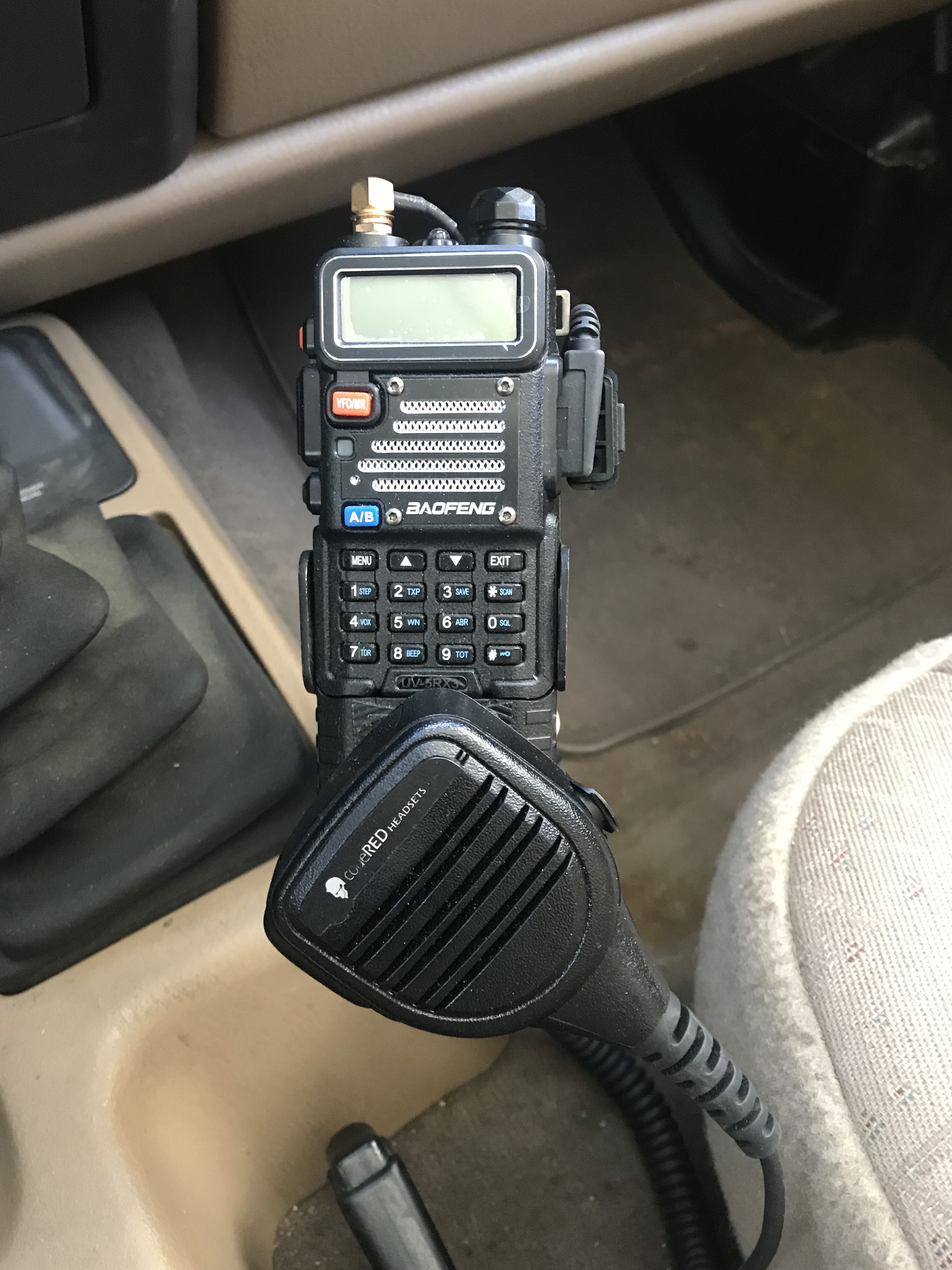
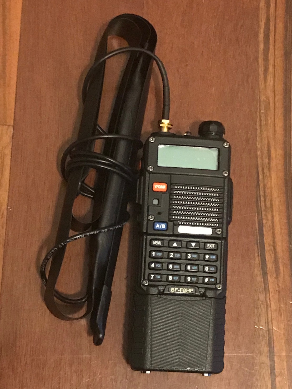
I had a Baofeng BF-F8 handheld attached to the antenna on this page. Sometimes people bash the Baofengs because they're so inexpensive, but I've had no problem with them...programming with CHIRP, hitting repeaters, etc. In fact, largely because of the antenna on this page, the Net Control Station for the emergency reporting net mistook my Baofeng for a Yaesu at a time when I was surrounded by terrain on all sides. Aftermarket antennas make a huge difference when using handhelds!
So one important lesson from this, which I've seen in several other disaster situations (I volunteer with a veterans' disaster response/recover organization) is that the community tends to come together and help each other in acutely tough times. Sebastian Junger even talks about it in his book Tribe.
Another important lesson is the helpfulness of the amateur radio community in general. We lost power at the house right before we left to get my son, and we had no cell phone reception to check the website for estimates on when power would be restored. Since my other son was staying at the house, I wanted an estimate so I could plan for contingencies. So I got on the Baofeng and hit the repeater, asking if anyone with access could check for me. That worked great!
There's terrain between my house and the repeaters, so I need all the elevation help I can get. I don't have a permanently-mounted antenna outside, but I improvised. I put a Nagoya UT-72 magnetic-mount antenna on a metal cookie sheet in a second-floor window, and I usually get reports of "full quieting into the repeater" that's about 15 miles away. Huge difference! It requires an ;">SMA-male to UHF-female (PL-259) connector cable or other adapter to connect to the antenna to the Baofeng.
Back to the Truck Install: Two More Decisions
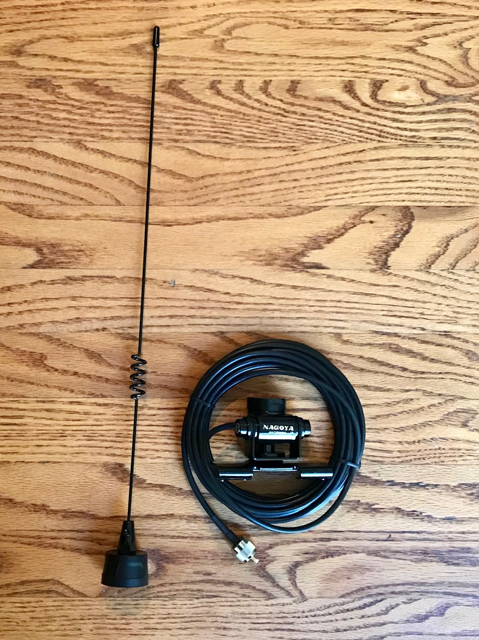
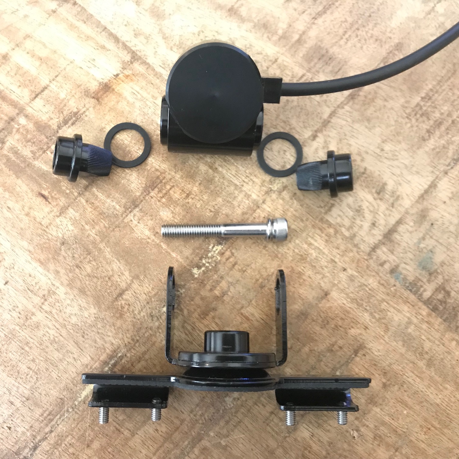
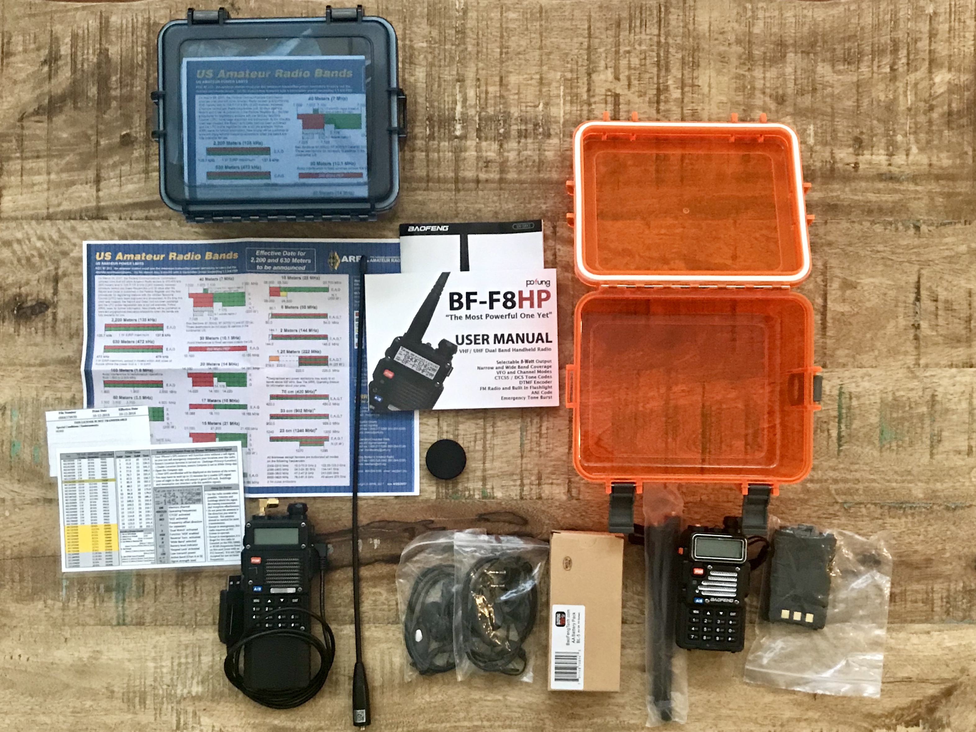
Pic 1: Equipment to install.
In addition to the antenna and mount, be sure to order cable and the appropriate radio connector. The RB-700N Multi-Axis Mount I ordered includes 20' of RG-58A/U Cable with a PL-259 Connector so I didn't need any extra parts. It also comes with a rain cap in case I need to remove the antenna to fit into a parking garage, car wash, under tree limbs, etc.
Before begining the install, it's important to make two key decisions. First, decide which side you want the cable to exit the mount. In this picture, it's coming off the left side. If this mount were to go on the passenger side of a vehicle (left-hand drive, like in America), the cable would be facing the front of the vehicle. Since I don't want the cable coming out the front, I'll need to switch it. Pic 2, below, shows how to do that.
Second, there are notches between the clamps. With thinner cable, like RG-174, you could run the cable between the clamps and reduce the profile somewhat. Depending on the connector at the end of the cable, this might mean disassembling the mount. I did not need to do that because the RG-58 is too thick, but I show the disassembly in Pic 4.
Preparing the Mount
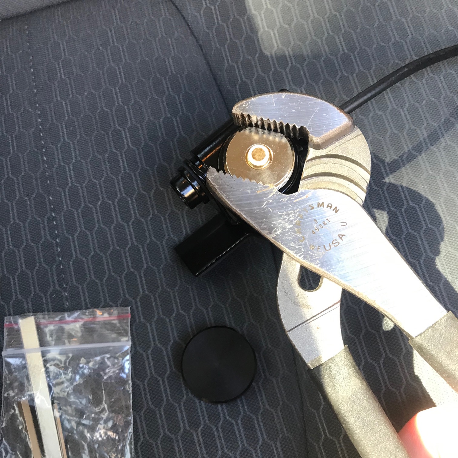
Pic 2 (below) shows how to change which side the cable exits the mount. The top nut of the NMO mount (where the antenna screws onto) has a flat spot on each side of the nut. Channel locks can remove this nut without damaging the threads. Just take it off, move the cable to the other side, and put the nut back on. I tightened it just a little more than finger tight.
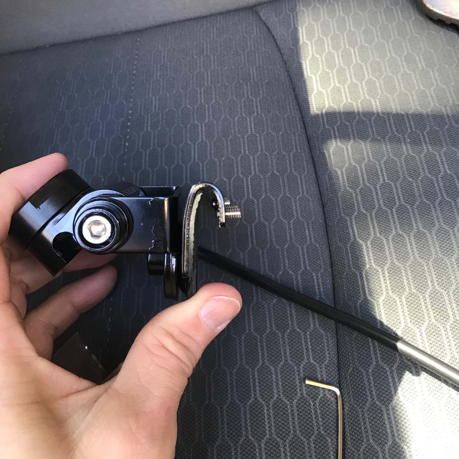
Pic 3 is just a sideways view of the mount. The cable will sit snugly inside the curve of the mount, at the top in this picture.
Pic 2: Switching cable exit.
Pic 3: Sideways view of mount.
Detailed Views of Mount
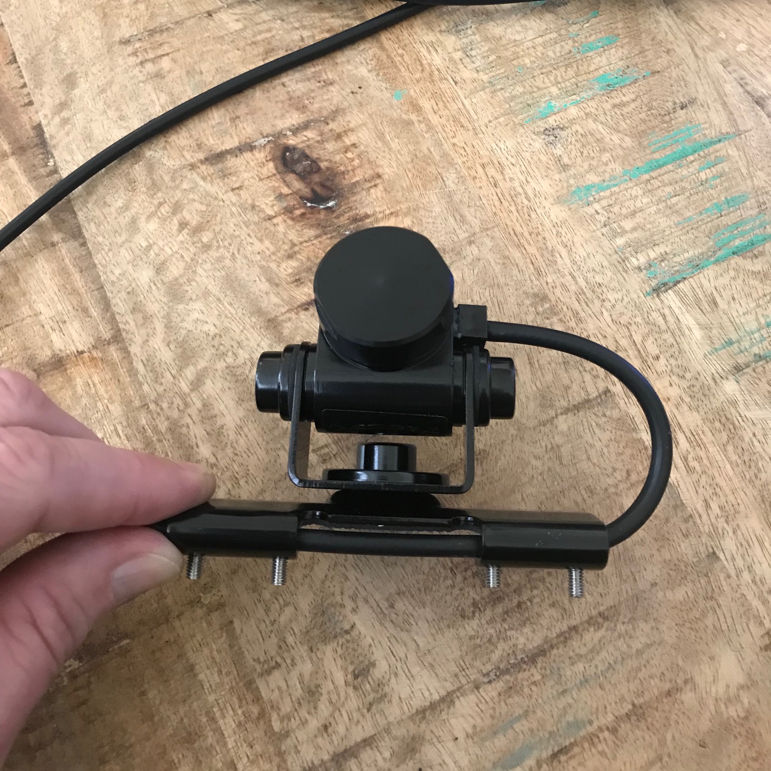
Pics 5 and 6 below show the mount ready for install on my truck. The cable exits the mount towards the rear of the truck, and it's tucked into the curve at the top of the mount. I didn't take pics of the next step, but I just slid the mount over the lip of the door and tightened the set screws...it's pretty simple.
The mount comes with a metal shim between the set screws and the rubber coating inside the mount. This could be used during installation to protect the paint from the set screws digging in. I chose not to use this protector because in my environment, it would retain a bunch of dust that would abrade the paint and cause damage anyway. I'm sure the screws will cause some damage to the paint but it'll be on the inside of the door, and it will be four small dots that will be just as easy to repair than a ~4" long series of scratches. But I probably won't need to repair it anyway.
Pic 4: Exploded View
Pic 5: Top View
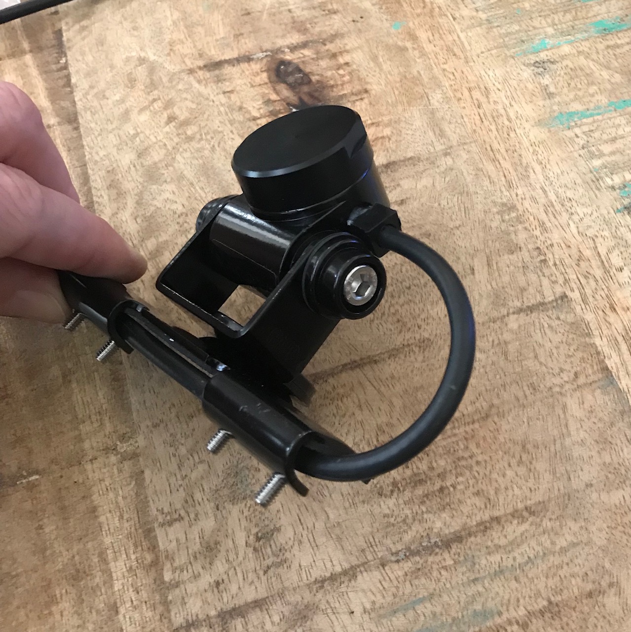
Pic 6: Oblique View
Pic 6 shows the hex screw used to tighten hinge that sets the vertical orientation of the antenna. You can also decide whether this screw faces the front or rear of the vehicle. I put it facing the rear to reduce the likelihood that debris gets inside the hex, like mud or a highway bug.
Routing the Cable Into the Cab
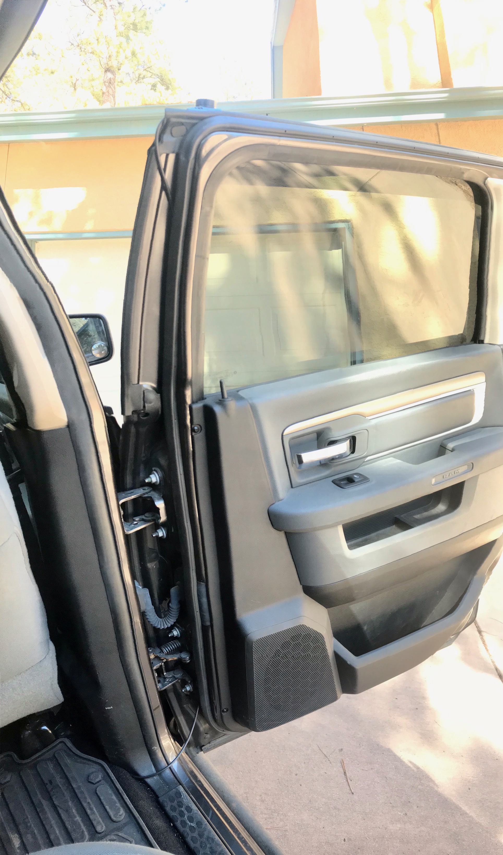
Pic 7: Full length of door.
This picture shows the full length of the door, and you can see how the cable enters the inner door space at the top and exits at the bottom. Immediately below are close-up shots of the top and bottom, and farther down you can see how the cable goes from the mount to the inside of the door.
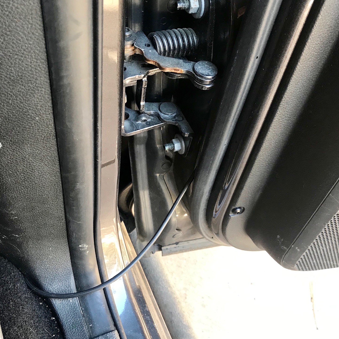
At the top of the door, the cable enters at a rubber seal; there is no metal-to-metal squeeze point here to pinch the cable. Once inside, I routed the cable behind the door seal. Since the cable enters the inner door space on the door's leading edge, and since there's no drip loop on the cable, there may be a small chance on rain running down the cable and inside the door area. If this happens, however, it should remain outside the vehicle and run down the cable on the outer edge of the seal, and then drip out the bottom without entering the cab. But there's still a risk, which is one advantage to routing the cable on the leading edge--water would pool in the floor in front of the seat where it's visible, rather than behind the seat were it might ruin things stored back there.
At the bottom, I left enough play in the cable so it will not be strained when the door is fully opened. I routed it through the trim behind the passenger seat, then under the passenger seat to come out next to the center console. You can find more detailed pictures of that below as well.
There does not appear to be enough pressure for the door to create a pinch-point in the cable, but I'll update here if I see evidence of it over time.
Pic 8: Top of door.
Pic 9: Bottom of door.
Routing the Cable Inside the Cab
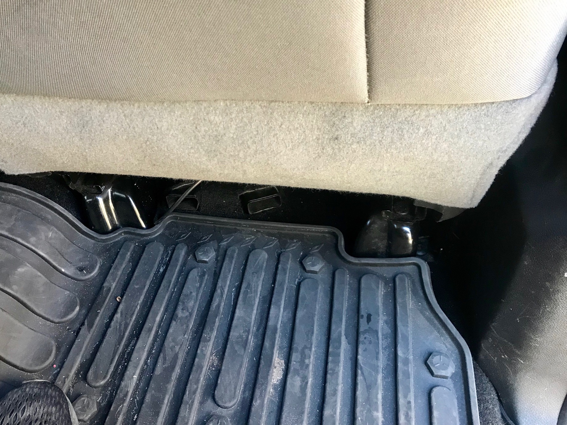
Pic 10: Passenger side cable.
Please excuse the dirty floor mat...haha! (They're WeatherTech mats, by the way...a little spendy but worth every penny when you live in snowy or muddy areas!
This is the rear floorboard on the passenger side, showing how little you can see of the cable. It enters the door as depicted above (seen in the bottom right of Pic 10), goes under the front passenger seat from the right side, and comes out from under the passenger seat right next to the center console. It then goes under the floormat, over to the driver's side, and goes between the driver's seat and center console as shown in Pic 11.
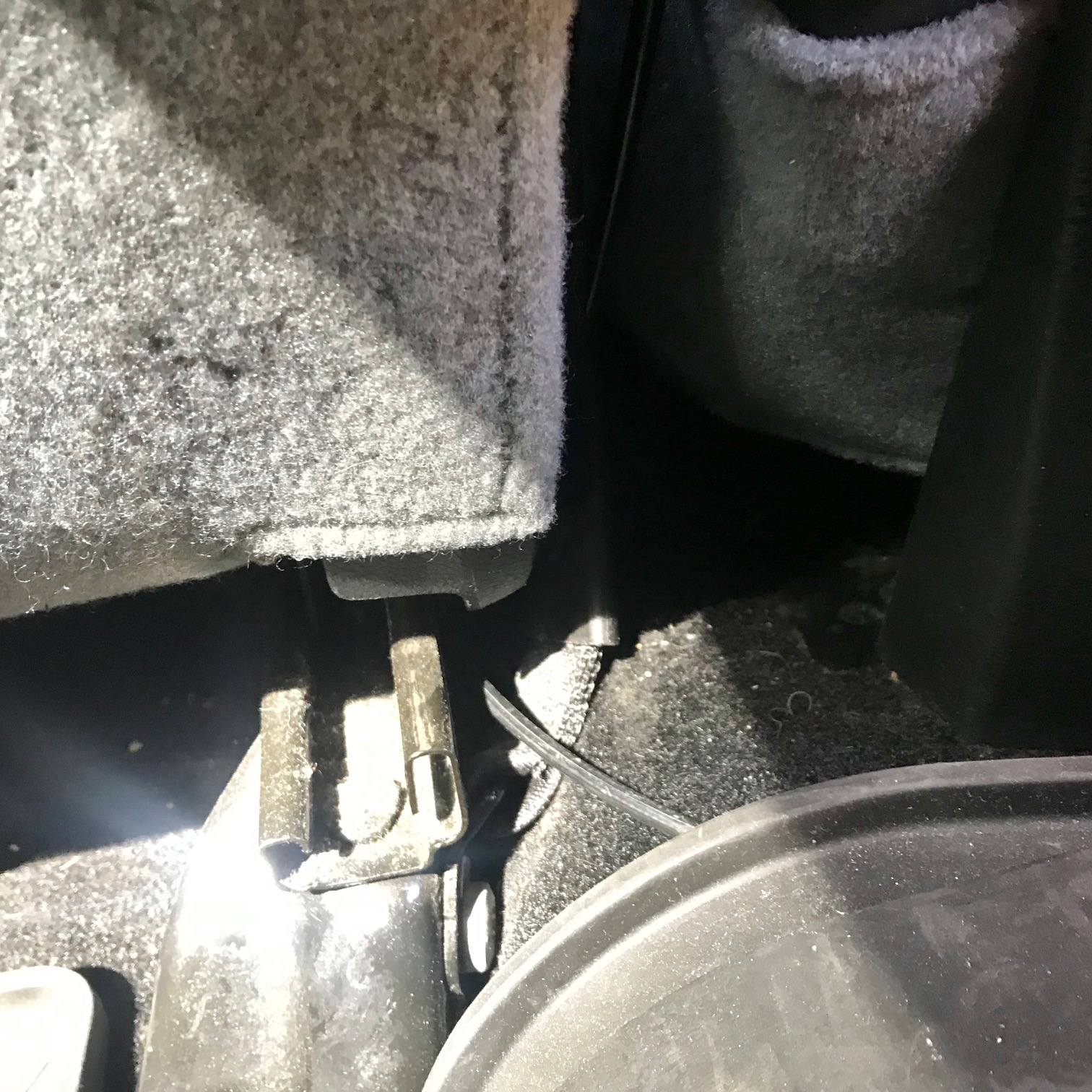
Pic 11: Driver's side cable.
That's how much of the cable you can see exiting the floor mat and going toward the front of the truck. I didn't take pics of the cable coming out from under the front of the driver's seat, but it just comes out from between the seats and straight to the radio. Since the cable runs between the driver's seat and the center console, it's completely out of the way. I'll put better pictures of this when I make a post showing how I mounted the radio and iPhone on the center console.
One important note for routing cable: avoid making coils with the extra cable. It's tempting to coil the extra cable and stow it under one of the seats, but coils can induce a current that affects transceiving. It's best to trim the cable to the exact length you need, but that requires having the means to install a connector and I don't have good quality crimpers right now. So I just bought the ready-made materials from Amazon and ran the extra cable under the floormat without creating any coils. It works.
Installation Complete!
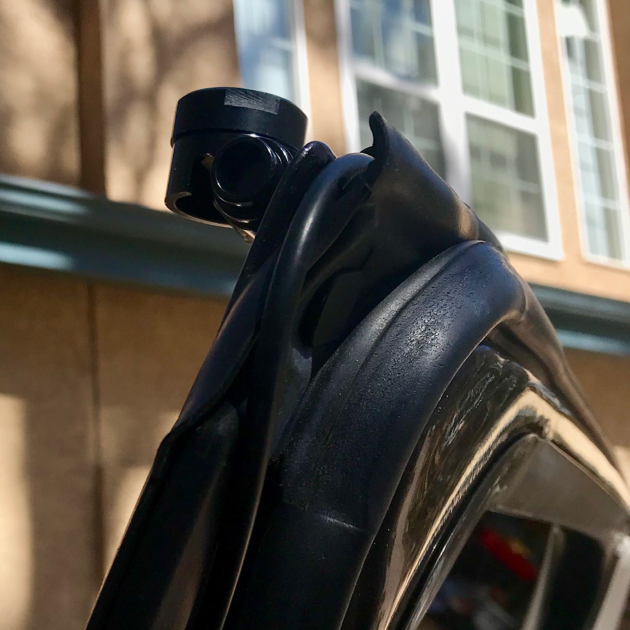
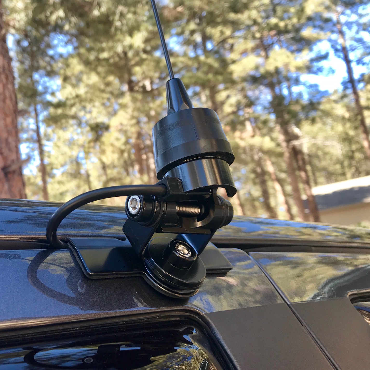
And here's the finished product, installed and ready to go! Pic 12 shows the forward edge of the door, and how the cable routes through the trim without getting pinched. In Pic 13, you can see how the cable enters the niche in the mount so it's protected from damage, including being pinched by the door.
Pic 12: Installed, front view.
Pic 13: Installed, rear view.
Pic 14: Installed, side view.
In Pic 13, you can also see both silver hex bolts that adjust the antenna orientation. The one on the far left adjusts the antenna's angle from left-to-right (as seen from sitting in a seat in the truck), and the one below that adjusts the antenna's orientation fore and aft. This way, you should be able to get a completely vertical antenna on most mounting surfaces.